

Watch the videos for this tutorial: Part 1A | Part 1B | Part 1C
MIDI?
Your EWI is a MIDI device, even if it has a self contained sound generator or sound source module. MIDI (Musical Instrument Digital Interface) is an industry-standard protocol that enables electronic musical instruments (synthesizers, drum machines), computers and other electronic equipment (MIDI controllers, sound cards, samplers) to communicate and synchronize with each other.
Unlike analog devices, MIDI does not transmit an audio signal: it sends event messages about musical time, pitch and intensity, control signals for parameters such as volume, vibrato and panning, cues, and clock signals to set the tempo. As an electronic protocol, it is notable for its widespread adoption throughout the music industry. MIDI protocol was defined in 1982.
All MIDI-compatible controllers, musical instruments, and MIDI-compatible software follow the same MIDI specification, and thus interpret any given MIDI message the same way, and so can communicate with and understand each other. MIDI composition and arrangement takes advantage of MIDI and General MIDI (GM) technology to allow musical data files to be shared among many different devices due to some incompatibility with various electronic instruments by using a standard, portable set of commands and parameters. Because the music is stored as instructions rather than recorded audio waveforms, the data size of the files is quite small by comparison.
Your EWI transmits the following types of MIDI messages: (all references here are to the EWI4000S, and in some instances may not be accurate to your particular controller. Please read your user manual thoroughly to have an accurate understanding of what MIDI controller messages your device transmits)
Breath Sensor:
Volume (07)
Expression (11)
Aftertouch
Breath control (02)
Velocity data
Other Sensors/Switches:
Vibrato (bite sensor)
Portamento
Pitch Bend
Sustain Switch (can be used to sustain notes or can also be used to transmit a specific MIDI CC# event)
Octave Switch (can be used to double notes in octaves or can also be used to transmit a specific MIDI CC# event)
Program Changes via MIDI Out
Depending on your setup and your performance preferences, you can activate all of these different controllers and use them to control your sound source(s) i.e., soft synths, synth modules, etc. Since just about every soft synth or sound module that is available today can take advantage of these controller messages, it is possible to program some extraordinarily expressive sounds by assigning filters, oscillators, effects and other sound manipulation tools to respond to these controllers.
In its most basic form, when you strike a single key on a keyboard, the keyboard transmits a single note-on message to the sound source with the pitch definition (C3, B2, D5, etc.), the speed (velocity) of the key (usually interpreted as the volume of the note, but can also include control of timbre), the length of time the note is held, and the pressure applied to the key while being held (aftertouch/key pressure). Some synths can be programmed to respond to the note-off velocity as well. The synth then interprets these numbers and based on that information generates a sound.
Your EWI does exactly the same thing but with several additional sensors, all of which can be brought to bear on a single sound source, making for some truly amazing sound design! Weʼll dive into sound design and programming soft synths in Logic in a later tutorial. Where the fun comes in beyond just programming sounds, is that you can use all of those available controllers to manipulate functions and objects in real time in Logicʼs environment. Thatʼs what this series of tutorials is all about, so letʼs get started. http://www.youtube.com/watch?v=bU5MirpfnLY
THE ENVIRONMENT
For an incredibly thorough and exhaustive tutorial on the basics of the environment, check out this tutorial by Toby Pitman. I was going to write an overview myself, but he has done such a fantastic job of illustrating the basics, it just made no sense to repeat his work. As a teacher, I find that people either work extensively in the environment or are completely terrified of it! It can be daunting for sure, but once you understand the environment in concept, it becomes much clearer how to use it and you begin to realize the truly awesome potential it brings to your creativity.

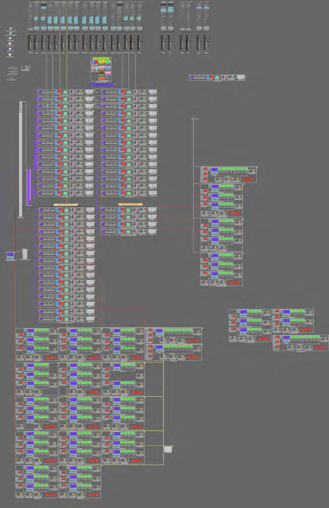
The “Itʼs An EWI Christmas” environment – what a mess!
The environment above was the environment I used to create the EWI Christmas video. As you can see, itʼs a complete mess! I was attempting new things, constantly tweaking and changing stuff over ad over again to get it to behave as I wanted it to. In retrospect, itʼs a miracle I was able to accomplish anything with this. My current environment looks like this:
As you can see, itʼs just a bit more organized! Some important things to consider when working in the environment are to keep your objects neatly organized in a visual layout that makes sense to you. You should also name your objects! Thereʼs nothing more frustrating than trying to find a specific object but only seeing 50 items names “transformer!” youʼll save yourself much frustration and time if you establish a naming and grouping system right from the beginning.
LET’S GET STARTED
Iʼm going to assume you have a basic familiarity with the environment and how to create new objects and link (cable) them together. For more in depth information, look at the Toby Pitman tutorial, study the Logic user manual, take a look at the resource links here and do some research online. Youʼll find a multitude of great resources for working in the environment. Open up Logic and create a new, default document. Create a new software instrument and select an ES2 instrument, ideally a brass or lead sound. Save it and give it a unique filename that youʼll remember. Then go to WINDOW> Environment or press Command+8. You should see this:

A basic environment window
In the upper left corner in the inspector, choose Clicks & Ports from the drop down menu:

In this window, you will see your hardware MIDI interface (1), a virtual keyboard that allows you to trigger notes from within the environment (2), a monitor object (3) that shows you all the MIDI data that is passing through it, and the sequencer input (4) which is the recording destination of all that MIDI information that comes into Logic. The environment is always in use – in this case in its simplest form. MIDI comes in through the hardware interface (1), passes through the virtual keyboard (2) and the monitor object (3) and goes into the sequencer input (4) to be recorded. The fun with Logic and the environment comes from the fact that between the physical input and the sequencer input, you can “put stuff in the way” of that signal, process it, mangle it, transform it and make it do wonderful and strange things. So the next step is to begin “putting stuff in the way!”
Weʼre now going to start building the elements to create a MIDI channel strip, like the ones seen in my environment above:

The first object is simply a text fader with all the possible program change numbers #00 – 127. It is simply a visual reference that allows you to set the incoming patch change number so you can know which patch change will activate that particular channel strip. It has no real functionality on its own. This MIDI channel strip has been compacted into a macro for ease of use and duplication; his is what the channel strip looks like unpacked:

You can see that the ## fader object has no input or output cabling, but is just sitting there as a visual reference. To create this visual reference, you would first need to create a new fader object in the environment window by selecting NEW> FADER> TEXT:

You would then see this:

By default, this text fader has the numbers 0-127 already embedded in it (see the range control to the left, in the inspector) and you can select a number by clicking and dragging up or down on the fader itself. For my purposes, I donʼt like to see single digits for the numbers 0 – 9, I want to see those displayed as 01, 02, 03, etc., since that is how my EWI (and modules) display patch change values. I always try to keep my visual references as consistent as possible in every location so I can avoid any confusion over what I am looking at and what any given number, slider, switch etc., actually means.
In order to make this minor tweak, you would need to open the fader objects value menu by double clicking on the fader. You would then get the following menu, the “value names of text” menu:

As you can see, I have filled out the first ten slots using 00, 01, 02, 03, etc. When finished, this fader will display 00-09 for the first ten digits and will resume itʼs own definition at 10. The RANGE value sets how many available “slots” there are in the fader. If you wanted to limit the available positions of the fader to only 00-09, you could change the RANGE limit to 0 – 9:

Would become:

This would limit the fader to only 10 positions and you would only be able to select numbers 00 – 09. For our purposes here though, I have set it to 0 – 127, since that is the range of possible program changes I can program on my MIDI foot controllers (Behringer FCB1010 and/or Digitech PMC10).
Lastly I want to color code this – remember, the easier something is to see the less confusing your environment will be – so I will open the color pallet by choosing Option+C. and I am going to choose purple for my color:

Now we have our first object! Congratulations!

Be aware that this object can still react to or send out MIDI, Fader or Meta data! I had to reprogram my entire environment because I forgot to change the settings on my text faders. They were jumping all over the place every time they sensed input because I had forgotten to change those values!

By default I always set these input and output parameters to Meta (Logicʼs internal data communication protocol), channel 16 and a value of 0. This insures that the fader will not react to any MIDI input, nor will it send any output to any other objects unless I specifically change these values to communicate with or take instructions from another object. For more about these settings, refer to your user manual or inline help and search for FADER OBJECTS.
http://www.youtube.com/watch?v=Au-FAzrMPbU SO…
SO… THAT WAS EASY!
Now for some fun! Weʼre going to create the first switched object in the channel strip, the Kill Vol object. While this looks like a single object, it is really a macro – several objects packed inside one. This handy little switch allows you to kill the volume parameter completely n any incoming signal. If youʼve ever hooked your EWI up to Logic, and youʼve had Volume (CC#7) enabled for the breath sensor output, youʼve most likely noticed that on whatever instrument channel youʼre addressing, the volume fader will jump up and down as you play each note and will fluctuate based upon how hard or soft you blow. Thatʼs because all of Logicʼs faders respond to CC#7 messages, and will react when they receive that volume message! Now in my MIDI channel strip, I have a volume kill switch AND I have a volume remap to modulation switch which allows me to either a) kill all the volume CC messages OR let them through and be converted to modulation CC#1. Hereʼs how you build the switch:

Unpacked, it looks like this:

The MIDI signal comes in through the ornament object titled MACRO IN (1). The swich/toggle (2) triggers the state of the cable switcher (3) to either off or on (position one or two) which sends the MIDI signal to the ornament marked as Through (4) or to the Transformer object labeled Kill Vol (5). The signal from either 4 (unprocessed), or 5 (volume CC stripped away) is then routed to the ornament object labeled MACRO OUT (6).
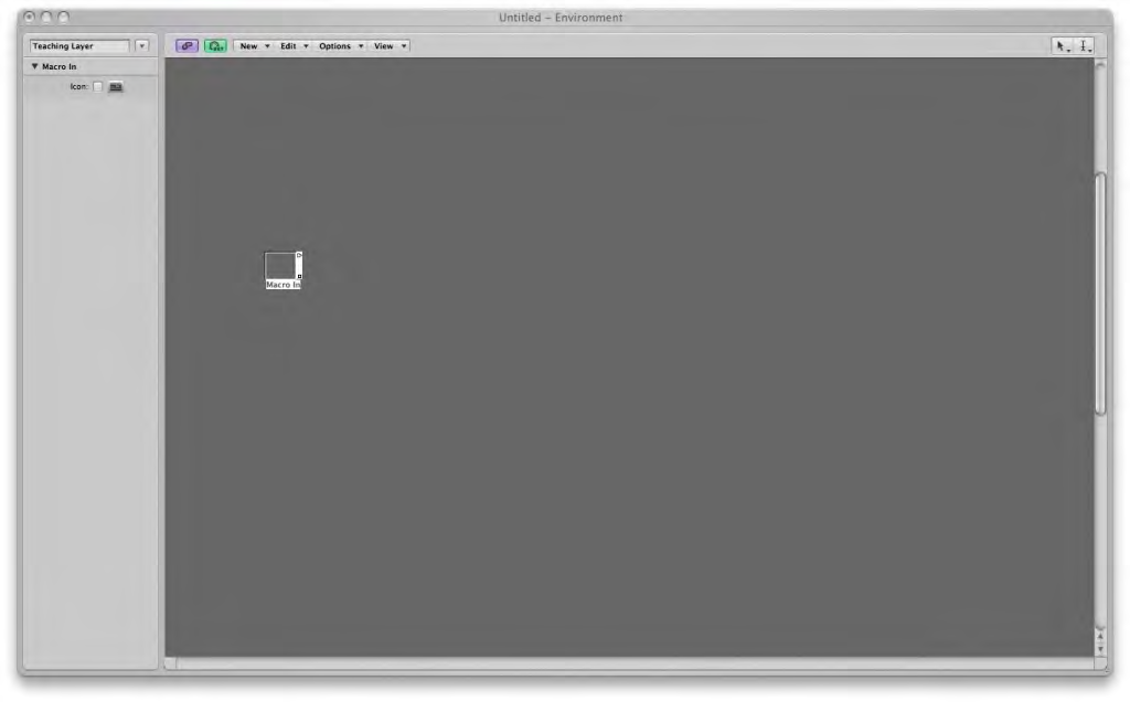
Step one: Create a new ORNAMENT object and name it MACRO IN. Ornament objects have no function on their own, they are used as placeholders, splitters or combiners of incoming or outgoing MIDI data. They act as useful nodes if you want to combine many signals into one destination or send one source to multiple targets. By naming the two ornament objects MACRO IN and MACRO OUT, Logic recognizes those as the first and last objects respectively in a MIDI signal path, so when you pack all the objects in a MACRO, MIDI would flow into the MACRO IN, be processed, and then flow out of the MACRO OUT.
Step Two: Create a new fader object: NEW> FADER> Button 3. Youʼll see this:

Command click on the name to rename it as ## (or whatever you prefer). In the fader definition inspector, change the values to be:
Style: Button 6
Output: Meta
Channel: 1
-1-: 7
Input: Meta
Channel 16
-1-: 0
Range: 0 1
Value as: Number
Filter: Off
Feedback: unchecked

Especially take note of the button style and the layout of the different tools. Experiment with many different buttons and see how, while they look somewhat different, they all function fundamentally the same way.
Step 3: Create a cable switcher. NEW> FADER> SPECIALS> Cable Switcher:

Connect a cables from the button and the ornament to the cable switcher. Set the cable switcherʼs input to the same output as our button, in this case META, Channel 1, #7. and set the cable switcherʼs range to 0 1. You may think “oh cool, now I can just hit this little on/off switch and my cable switcher will change positions.” Well, it doesnʼt! Thatʼs because, even though we have established the cable switcherʼs input control (Meta, channel 1, #7) and have connected our switch (our button object) to it, we still donʼt have any destinations to send to. If you look at the upper right corner of the switcher, youʼll notice there is only one output port.

Until we actually connect the switcher to more than one destination, thereʼs no second output for it to connect to! So create a new ornament object (NEW> Ornament) and call it “Thru” and create a new transformer object (NEW> Transformer) and call it “Kill Vol.” Connect the top cable switcher output to the thru ornament. As soon as you do this, the cable switcher will sprout a new output!

Connect this new output to the Kill Vol transformer. The cable switcher will sprout a third connection, but weʼre not going to use it. In any case, every time you connect an object by cabling them together, the source object will automatically grow a new output! What you should now have is something that looks like this:

If you click on the on/off button, the cable switcher will change to position one and change to look like this:

Congratulations! Now, every time you click the on/off button, the cable switcher will switch between the two possible output destinations, thru and Kill Vol.
THE 800 POUND GORILLA
Double click on the transformer object (Kill Vol). This will open the transformer definition which is where you will tell the transformer to kill the volume CC#7 data while leaving all the other MIDI data untouched. For an exhaustive and VERY thorough investigation of exactly what the TRANSFORMER object does, check out this tutorial, again by Toby Pitman. Toby explains in minute detail the functioning of each control and section in the TRANSFORMER. It is a must see/read for anyone who really wants to understand how transformers work.

Set the transformer parameters to: MODE: Filter matching events; STATUS = Control; CHANNEL All; STATUS BYTE = 7 (CC#7) and DATA BYTE All.

What you have just told the transformer is “Ok. I want you to analyze the incoming MIDI data and if you see Controller number 7 (Volume) data, on any channel, I want you to strip it out but pass everything else through to the exit.” Close the transformer definition window. Create a new ornament object and name it MACRO OUT, and connect the THRU and KILL VOL objects to it.

Now letʼs insert our KILL VOL object in the MIDI path. Drag around all the objects in our design and select EDIT> Copy or press Command+C to copy them. In the upper left corner, select the MIXER in the environment layers drop down menu. Select EDIT> Paste or press Command+V to paste our build into the MIXER layer. We now want to select, in the environmentʼs window, NEW> Physical Input. This will basically move the physical MIDI input from the Clicks & Ports layer and make it appear in the Mixer layer. Drag it to a good location on your screen where you can see everything. Connect the cable from the SUM output of the Physical Input to the MACRO IN of our KILL VOL object. Take the MACRO OUT output and connect it to the ES2 channel strip in the mixer window.

If your EWI is connected, and Volume is enabled in the breath sensor output, when you blow into the EWI, you will see the fader for the ES2 channel strip begin to jump up and down, based upon how hard or soft you blow. Now set the fader back to -0.0 db and engage the KILL VOL object by turning it on. Blow into your EWI. The fader doesnʼt move! Youʼve successfully stripped out the volume data from the data stream, and now the fader doesn’t react! This is a great way to enable volume CC#7 from your EWI without affecting the volume of your channel strip(s) while allowing you to remap the volume control to another controller. Next week, weʼll do just that – remap Volume CC#7 to Modulation CC#1.
PACKING IT ALL UP
Now that we know our Kill Vol widget works as it’s supposed to, we can pack it into a MACRO object to make it easier to move around and neater to look at. Drag enclose all the objects in the Kill Vol widget to select them. Then go to NEW> Macro

All of the objects get packed into a single box, which you can then resize to the optimum size for displaying its controls or information. We’ll resize the MACRO by grabbing the box in the lower right hand corner of the macro and dragging it to the new size we want. Then Command + click on the name to rename it “Kill Vol.”

Renaming:

Our completed environment:

That’s it! You’ve created two new objects for your environment!